The standard references for assembling the SmartiPi Touch are the videos by the creator, Thomas Murray, and and a more complete video by Francesco Vannini (both videos embedded at end for reference)
However, many commentators have noted that there is not a good set of written directions, and I think the big disadvantage of an expert commentator is that they don't always remember to say things that a non-expert may have a hard time figuring out. I mostly followed Francesco Vannini's video, so here are a few additional notes.
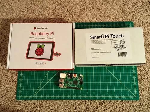
Here are the boxes, with a Raspberry Pi. Not pictured is the Sense HAT that I will also put on.
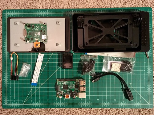
All the components from both boxes. Note that not everything will be used.
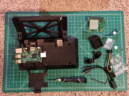
At this point I have:
- Added rubber feet to the corners of the stand (back side of the part that is mounted on the hinges).
- Attached stand to case body using included nut and bolt.
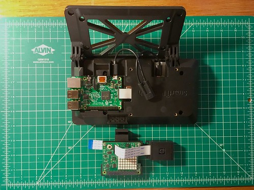
- Connected the display connector ribbon to both the display driver and the Raspberry Pi. I used the one that came with the touch display. I should have used the one that came with the SmartiPi case because it was longer and would have been easier.
- Mounted the Raspberry Pi to the display case. the instructions state I could either use the screws to mount the Raspberry Pi or I could use the hinge cover (bottom of picture). The cover has plastic that is sized to touch the Raspberry Pi when closed so I choose that option.
- Screwed the case back to the display. Note that one of the screws will be covered by the cover and any HAT so I tightened this now instead of waiting until the end to tighten everything.
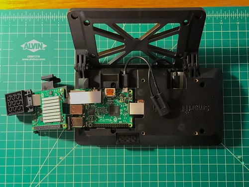
Raspberry Pi camera module with mounted Raspberry Pi and SmartiPi Touch case. Note that the ribbon that comes with the camera will be just long enough to mount to the top or side LEGO studs. A longer camera cable will be useful since the Raspberry Pi with display and case is going to be placed on a table top, which is not necessarily where you want the camera.
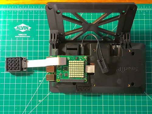
Here is the camera attached to the Raspberry Pi. Note that it goes through the slots in the door and the Sense HAT.
Now, attach the door, then mount the Sense HAT and tighten the screws on the Sense HAT. Note that the screws come with rubber spaces that put the HAT the right distance above the door.
Picamera added to Raspberry Pi in SmartiPi Touch Case on the top LEGO pieces. I used a 4X6 plate because it is long enough to reach the back LEGO mount for the top. (mounting to the side could be done with camera mount as is)

Pi camera mounted to LEGO from back
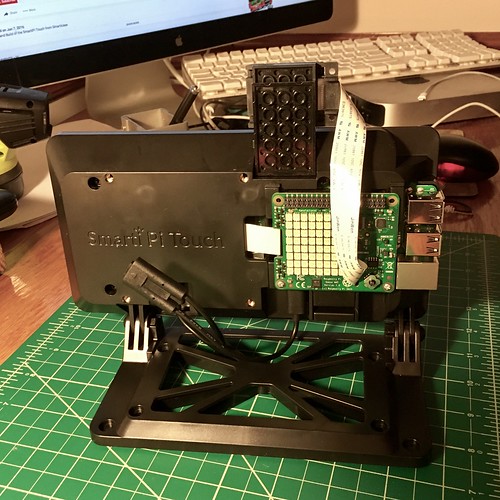
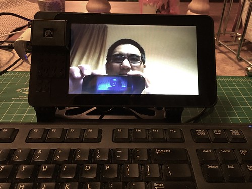
The working camera. Note that I have the whole thing running off a USB battery. I usually have this connected to a keyboard, and use a touch screen to serve as a mouse. It really needs a longer camera connector ribbon. I tried to mount it on a LEGO stand, but the SmartiPi case had to be right next to the stand.